
INTRODUCING THE LAKHOVSKY MULTIWAVE OSCILLATOR (MWO)
100% ELECTRICALLY CORRECT REPLICATION FOR THE 21ST CENTURY
MODEL MD-1F/UA – 6TH GENERATION!
MD = MODULATOR
1E = 1ST MODEL & F IS 6TH EDITION
UA = INVISIBLE RAYS
AVAILABLE WITH EITHER THE ORIGINAL COPPER RING ANTENNAE
OR
WITH ERIC DOLLARD’S GOLDEN RATIO PCB ANTENNAE
ALSO AVAILABLE IS AN OPTIONAL ADD ON
THE DOLLARD OSCILLATION TRANSFORMER
YOU CAN HAVE YOUR OWN “COSMIC INDUCTION GENERATOR“
THIS PAGE IS OBSOLETE
EVERYTHING IS BEING MOVED TO EMEDIAPRESS.COM
TO RECEIVE THE UPDATED PRICE LIST & ORDER DOCUMENTS
GO TO THE FOLLOWING LINK AND ADD THE FREE PDF
TO THE SHOPPING CART AND CHECK OUT
LAKHOVSKY MULTIWAVE OSCILLATOR (MWO)


A FEW VIDEOS ON THE LAKHOVSKY MULTIWAVE OSCILLATOR (MWO)
Early video of Eric Dollard assembling the first production prototype military-style pulse modulator for the MWO system and testing it. Audio starts at 53 seconds.
Introductory video reviewing the basic concepts of the Lakhovsky Multwave Oscillator. This is a walk through of the system and how it works. Coming soon…
Learn how the Lakohvsky Multiwave Oscillator is distinctly different from a Tesla balanced arrangement and why.
Two people in 10 minutes can setup the entire MWO system. Watch this video to see how simple it truly is.
Here is how to run the MWO on a battery for off the grid situations, semi-portable options or if you are overseas with 220v and 50hz.
This has a lot of the same info in the video comparing the Tesla Balanced & Lakhovsky Unbalanced methods. From 2019 ESTC with other details.
Assembly video with the * NEW * PCB Eric Dollard Golden Ratio Antennae complete with a Counterspace Demonstration at the end.
Latest assembly video of MWO with both copper and pcb antennae and the oscillation transformer.
SPECIAL THANKS TO PETER LINDEMANN, PAUL BABCOCK & ERIC DOLLARD FOR THEIR SUPPORT IN THIS PROJECT
THE LAKHOVSKY MULTIWAVE OSCILLATOR (MWO) EXPLAINED
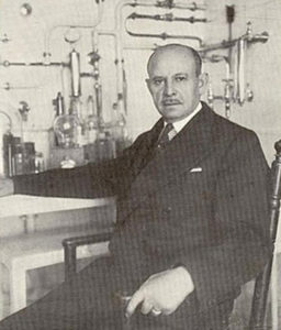 George (Georges) Lakhovsky was a scientist in the early 1900’s who discovered a connection between poor health and low soil conductivity. There is a voltage between the ionosphere and the Earth of a few hundred thousand volts. That can be a few hundred volts per meter up to 10,000 volts per meter in a thunderstorm for example. In order for the positive electrostatic potential of the ionosphere to properly ground to the Earth, the ground has to be conductive enough.
All living things grow and thrive inside of this electrical field but in the modern age of rubber sole shoes, the concrete jungle, chronic inside living, etc. we are not properly grounded and are not thriving as we should.
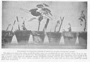 Some of the early tests Lakhovsky conducted were with plants that had undesirable growths on them from various ailments. He cut some copper rings and placed them around the plant’s base and in a few months, the growths fell off and the plants normalized.
There are a lot of frequencies that are naturally occurring around us all the time. Whatever frequency has a wavelength that is the same as the copper ring’s length or a fraction of the wavelength, that ring will resonate/vibrate at that frequency and the plant will benefit from this.
Later on, he advanced on this concept to create a machine that is beyond profound in terms of the implications of what it can deliver.
If we are able to have a machine that can give a high voltage electrostatic output have this travel through a subject to ground, then we can replicate not only a healthy ionosphere to ground electrical environment, we can take it many levels above for more than optimum results.
WHAT IS THE LAKHOVSKY MULTIWAVE OSCILLATOR (MWO)?
 George Lakhovsky started to develop a system that had Tesla-like properties. It had high voltage step up coils that were pulsed by a high voltage transformer that charged up capacitors and these were discharged over a spark gap to create rapid bursts of radio frequencies.
These impulses were sent to the concentric ring antennas, which are not electrically connected to each other. They are only capacitively coupled and they are not shorted rings, they have gaps. Remember the concept of the ring around the plant, each length of copper has it’s own resonant frequency based on wavelengths or fractional wavelengths.
To the left, you can see an old picture of really skinny rings and notice the strip going across the center to hold the rings in place rather than the strings – an early model to prove the concept.
As the high frequency, high voltage impulses are sent to the rings, there is a wide range of frequencies that are created in addition to the primary frequency that the unit is tuned for.
Anything in between the antennas is receiving Aether (source potential), which is polarized and oscillated back and forth between the antennas, extraluminally. That does not mean faster than the speed of light, which is “superluminal” – it’s extraluminal, which means it is outside of the fictitious light speed constraints. Make sure to watch the videos at the top of this page.
Many product makers and “experts” claim they are using “scalar waves”. The truth is there is no such thing as scalar waves and this is a scientific fact. A scalar is something that has a magnitude but no direction. For example, the temperature in your room is a scalar and so is the barometric pressure. It’s omnipresent in an area for example with a magnitude but there is no specific direction to it. That is what a scalar is and why the notion of scalar waves is complete nonsense.
The LAKHOVSKY MULTIWAVE OSCILLATOR (MWO), when built correctly, is one of the most coveted machines in the world and has been for nearly a century because it produces these extraluminal waves. The waveforms between the antenna are LONGITUDINAL WAVES – the real Tesla type of longitudinal wave that does NOT conform to the inverse square law nor they have a velocity in this application. They transmit extraluminally from one antenna to the other without taking time to get there. If there is no time then velocity is not part of the equation. It is not transmitting through space, but rather through counterspace from point A to point B.
LAKHOVSKY PATENTS THE MWO
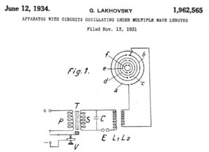 George Lakhovsky did indeed patent his invention but it was very early before he evolved it to its ultimate evolution, which is what we are making available. Plus, patents only cover the claims and rarely ever show the “secret sauce” recipe as to how the machine is really put together or what the actual secret electrical circuit is. Every great inventor keeps a bit of the know-how to themselves for proprietary reasons. Many people over the years have attempted to recreate the Lakhovsky Multiwave Oscillator (MWO), but they all failed in nailing it because most are trying to replicate his patent diagram or a variation thereof.
This is not to say there is no benefit to these false “MWOs” because it is possible that there could be to a small degree. However, it wasn’t until about 2008-2009 timeframe that Lakhovsky’s crowning achievement was discovered. We’ll get to that shortly.
LAKHOVSKY MULTIWAVE OSCILLATOR (MWO) RESURRECTED
Bob Beck, a prolific researcher in the alternative science field, is someone who got the conversation going about Lakhovsky’S Multiwave Oscillator (MWO) when hardly anyone even knew about it. One thing led to another and even George Van Tassel who created the Integratron based his strange and very famous building and it’s electrical operation on Lakhovsky’s MWO research. Bob Beck new some who were involved with Borderland Sciences Research Foundation who had members such as Peter Lindemann (my long time friend and business partner who recently retired) and others who sold articles, books and devices based on the best information available at the time. Eric Dollard (another long time friend and partner) was also a member of Borderland and he was also the last engineer tasked with carrying out George Van Tassel’s plans with the Integratron.
Around 2008 in Europe, a few engineers were connected to someone that had some original Lakhovsky Multiwave Oscillator (MWO) machines crated up. These were the crowning achievement (aka – the REAL MWOs) of Lakhovsky that achieved his claims and keep in mind, WE MAKE NO CLAIMS. It was reverse engineered and the first person to build these units and make them available to the public was from Croatia (a friend of mine who helped me with some projects in the past) – someone that was a master engineer and craftsman. They’re built correct, but are very large and bulky because they they are built in the spirit of the early 1900’s MWOs and are very expensive. A friend in Seattle bought one and by the time he received it, the cost was substantially higher than the VRIL MWOs. If you want something that looks more like the original unit, my friend’s is the one to have. However, our friend brought it to our shop to get diagnosed since it stopped working and to our surprise, the output strength was quite a bit less than the VRIL MWO. I think it is because the universal power supply that can be wired for 110vac in the states is designed originally for 50Hz and it doesn’t work very well for 60Hz. Keep in mind that this Croatian MWO is the FIRST ever commercially available MWO that is built not just to spec but with the correct circuit and it’s BEAUTIFUL!
THIS PAGE IS OBSOLETE
EVERYTHING IS BEING MOVED TO EMEDIAPRESS.COM
TO RECEIVE THE UPDATED PRICE LIST & ORDER DOCUMENTS
GO TO THE FOLLOWING LINK AND ADD THE FREE PDF
TO THE SHOPPING CART AND CHECK OUT
LAKHOVSKY MULTIWAVE OSCILLATOR (MWO)
Shortly thereafter, someone in the Northern mid-west started to manufacture these systems based on the same information. The builder makes possibly one machine per month and they’re nearly $5000.00 USD. But they’re in a wooden box and it’s all a bit flimsy. The coils and antennas are on a stand in a way that they’re very top heavy and are about to fall over. The high frequency line filter inside of the pulse modulator was hooked up incorrectly and every time it was turned on, the wireless phones, routers and other electronics in the house went haywire. We know this to be true because it was Peter Lindemann who has had this machine for several years and these problems were persistent until he rewired it himself in order to correct the problem by putting the line filter where it was supposed to go. Even with the line filter, this kind of machine has no business being in a wooden box if it is for sale to the public. If you’re making one yourself for personal use and you have it out in a barn away from anything electronic, that’s one thing. But selling these to others to put in their homes or businesses is not the way to go. Keep in mind that this wooden box MWO is the SECOND ever commercially available. However, because the line filter was not wired up properly, it can’t be taken seriously as a legitimately built, proper MWO. Furthermore, the claim on the website is that it is the ONLY one built to the exact specs as Lakhvosky’s but we all know that isn’t true – there are multiple companies including our own that makes the real thing. That company is using the same reverse engineering report that we used. THIS COMPANY IS NO LONGER IN BUSINESS.
At some point, a Russian company started to make a MWO and I found out about it and researched it a bit and it appears to use the correct circuit but is also very expensive. I found out about this because the company owner kept spamming my YouTube channel’s MWO videos with advertisements for his website. As tacky and desperate as that is, it appears to be a correctly built unit. Keep in mind that this is possibly the 3rd or 4th ever, commercially available legitimate MWO. We’re not sure if they started building theirs before or after ours. WE CAN NO LONGER FIND DETAILS ON THIS COMPANY.
We thought a company in The Netherlands started to make the real thing but it appears they’re just a reseller for my friend’s company from Croatia.
The reason I made a point to listing the above-mentioned legitimate units is because these all were only made possible because of the reverse-engineering report that was produced AFTER the REAL Lakhovsky Multiwave Oscillator (MWO) units were found.
Also, what this means is that all the claimed “MWOs” made in New Zealand, Australia, and elsewhere are phony, misrepresentations based on nothing more than speculation and hype. 100% of all of them fail to ground one of the phases on the HV output just like Lakhovsky did – not only that, they didn’t even know about it and the one in the Netherlands has the audacity to claim they made an improvement on the MWO. Even after the real information came out, these companies continue to knowingly mislead the public into believing they are building a Lakhovsky Multiwave Oscillator (MWO) when they are in fact not! If you want to know what the grounding of one phase is and what it isn’t – make sure to watch my videos at the top of the page regarding BALANCED vs UNBALANCED. Lakhovsky’s MWO is an unbalanced system and this is an indisputable, historical fact.
 Moving forward to where our MWO development came from… Peter had been using the wooden box machine for quite a while, had it over at Paul Babcock’s (a long time friend and partner) shop so others could try it and Paul committed to making his own so he could experience and study it long term. Paul used it for one to one and a half years and gathered a massive amount of data on it, how it performed, etc., which he spelled out over the course of three different presentations called The Universal Medium, The Living Earth and Beneficial Field Technologies. Again, we make no claims whatsoever and only offer our Vril MWO as an electronic test device so you can study how Lakhovsky made his waveforms.
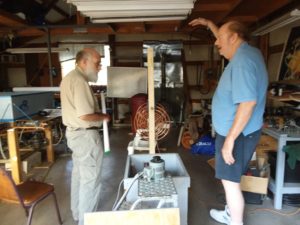
Paul’s home-brew MWO built to the real Lakhovsky specs is in the picture to the left. Eric Dollard and Paul Babcock are talking shop.
We were so astonished at to how perfectly it replicated Lakhovsky’s waveform and we committed to making it as easy as possible for people to put these machines in their hands, which has never been done in history at any significant level and that is how we got started. Paul’s personal build and the real specs on Lakhovsky’s MWO were the inspiration for a project that continues to this day.
MWO Test
Once we had a chance to orient ourselves to all of the information, Eric Dollard, the modern day Tesla, engineered the production model prototype that all our production models are based on. Just about all of it is made right here in Spokane, Washington. You can see some of the early prototype development in the video at the top of this page where Eric is assembling the Pulse Modulator in fast forward speed. That was a video that was released when extra funds were needed for development and we had no choice but to sell the original unit. We offer the video for posterity sake.
BRINGING THE MWO INTO THE 21ST CENTURY
If you want a unit that is designed in the spirit of a military-style pulse modulator by Eric Dollard, the world’s leading authority on Tesla technology, with all proper shielding and grounding practices incorporated in a compact unit that is not only sleek and simple for a very reasonable price and with craftsmanship that is top-notch, then you’ve come to the right place. Not only is our price reasonable, it’s a fraction of what the other legitimate units cost.
PULSE MODULATOR
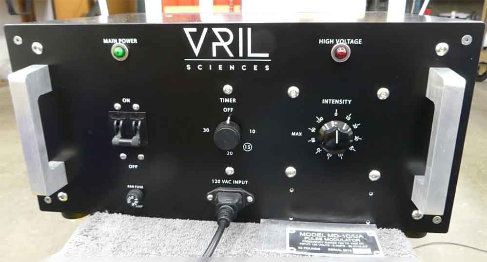
3rd Generation Pulse Modulator designed by Eric Dollard
The Pulse Modulator is at the heart of the Lakhovsky Multiwave Oscillator (MWO). Wall power goes through some filters into a variable AC transformer. This feeds regulated voltage into a high voltage transformer, which has an output going through some filter chokes that prevent RF noise from feeding backwards into the transformer to prevent it from burning out. The chokes feed a spark gap and capacitor array, which then delivers this output to the the high voltage, step up resonator coils.
Eric Dollard designed the layout of the inside of the pulse modulator. Because of Eric’s extensive mastery of high voltage and high frequency devices, our pulse modulator is unique in that the low voltage and high voltage section inside are separated and shielded from each other. It is known by advanced engineers that this is standard practice, but there are no other MWOs that are made with this feature – it is unique to our MWO system.
The reason this is an important feature is that any of the high voltage high frequency section components, spark gap emissions, etc. can easily induce noise into the low voltage components. Every low voltage component wire is an antenna that can pick up the high frequency emissions. Preventing or reducing this to a bare minimum extends low voltage component life, reduces noise that can feed back into the wall outlet and overall shielding with the case in general greatly reduces much of the RF noise emissions.
The spark gap is also adjustable, which varies the spark gap frequency and current impulse power.
NOTE: IN FUTURE UNITS, WE MAY SWITCH TO A NON-ADUSTABLE SPARK GAP UNIT.
THIS PAGE IS OBSOLETE
EVERYTHING IS BEING MOVED TO EMEDIAPRESS.COM
TO RECEIVE THE UPDATED PRICE LIST & ORDER DOCUMENTS
GO TO THE FOLLOWING LINK AND ADD THE FREE PDF
TO THE SHOPPING CART AND CHECK OUT
LAKHOVSKY MULTIWAVE OSCILLATOR (MWO)
PULSE MODULATOR IS UNIVERSAL
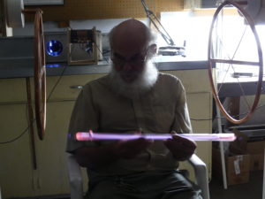
Eric Dollard testing MWO with Capacitor Rings
The Pulse Modulator is not limited to its use for the Lakhovsky Multiwave Oscillator (MWO). As you can see in the video at the top of this page comparing the balanced Tesla method and the unbalanced Lakhovsky method, they both use the same pulse modulator. We will be offering the balanced coil arrangement at a later time so that you can conduct Tesla experiments with the same pulse modulator. This is for high voltage output demonstrations, replicating Eric Dollard’s Cosmic Induction Generator technology and other related systems.
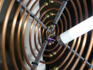
OSCILLATION TRANSFORMER AVAILABLE AS AN ADD-ON FOR BALANCED MODE
We are now producing the balanced coil Oscillation Transformer as an add-on to the normal MWO system. It is available for an extra fee and is only available to those who purchased or are purchasing a new MWO system. There is no way to have the MWO system come with the balanced arrangement instead of the Lakhovsky unbalanced arrangement so it can only be an add-on in addition to the full MWO system.
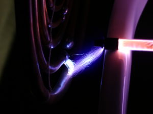
Here is a brief video demonstration to show what it looks like and you will see a black spot appear in the fluorescent tubes. That black spot is an example of “Counterspace”, which is the inverse of space. In common language, it is literally a point of entry into a different “dimension” and we are the only ones in the world offering this simple add-on for a MWO that allows you to demonstrate this for yourself. Switching between the unbalanced Lakhovsky mode and the balanced mode takes less than 5 minutes and with every other MWO, you’re stuck with only the Lakhovsky mode.
This video is posted at the top of this webpage to show you how to assemble the MWO with the Eric Dollard PCB Golden Ratio antennae and it is here again because if you fast forward to the last segment, you can see the counterspace effect with these antennae as well.
Essentially, when you have the balanced Oscillation Transformer as an add-on, you have a Cosmic Induction Generator, which is a whole other topic but to give you an example of what that means, watch this excerpt from this presentation from Eric Dollard and I, which was presented at my 10th annual conference – the 2021 Energy Science & Technology Conference. I’d recommend that you get a copy of this presentation because it is the most in-depth presentation ever given that discusses and demonstrates the Neutral Spot. The MWO doesn’t have audio modulation and there are other differences, but you ABSOLUTELY have an opportunity to experiment with the neutral zone if you wish when you have the Oscillation Transformer add-on. Check out this excerpt here:
COILS
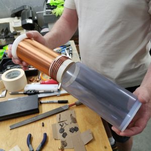
MWO Coil Assembly
The coils are designed with effective dielectric materials (insulators) to lock in the high voltage into the coil assembly so that the maximum amount of voltage can be directed to the antennas. Whatever loss or leakage happens at the coil assembly represents a loss that will not make it to the antennas.
The plastic materials are selected so they also do not heat up with the high frequency, high voltage pulsing fields.
The coil windings are also painted with 7 coatings of Super Corona Dope, which is the best wire coating available in the industry that prevents corona loss and leakage and keeps the wires in good shape for many years.
The output voltage of these coils is 250,000 to 300,000 volts at maximum, but normally the unit does not need to be pushed this much. Most users prefer the Variac Intensity setting to be around 50% with a spark gap setting at 50%.
ANTENNAE
MWO Antenna
COPPER RING ANTENNAE – There is an art and science to properly crafting the antenna, which are the most difficult parts to make for the MWO system. Classically, the antennas are tied together with string/twine. Some of the thought is that it has the least interference to the frequencies pulsing at the antennas. The antenna are a bit clumsy when wired together with string, are easy to become damaged during shipment, they wobble quite a bit when/if bumped and if the antenna/stand structure fall over, there is great risk that the strings could be damaged and they will have to be restrung at the owner’s own cost.
We are using HDPE strips to hold the antennas together – HDPE is an excellent dielectric (electrical insulator) and it is also resistant to carbonizing in case someone gets too excited with making sparks on their antennas. If there is carbonizing of the plastic, then it become conductive and the rings will more easily spark from one to the other following the carbon trail left behind. The strips are stronger than the string, more rugged, keep the antenna intact during shipping and there are other obvious benefits. On an engineering level, we determined with Eric Dollard that as long as the total width of all four strip pairs (front and back) are less than 1% of the total circumference of the antenna, it offers no significant change to the MWO’s operating frequency.
The antenna are made of copper and are meticulously bent at very strict specifications to match those of Lakhovsky’s own BV2 model. We matched them up side by side with the European model mentioned above and it is quite uncanny that they are virtually IDENTICAL in tube width and spacing. We held up a strip to the European ones and it would actually work on those! To engineer that kind of perfection from details from a report without ever having a real model to copy from is testimony to the craftsmanship that goes into every one of our VRIL MWOs!
These are available at a higher cost – the lower cost PCB Antennae perform the same but are available at a much lower cost.
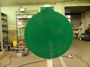
Lakhovsky MWO – Eric Dollard Golden Ratio PCB Antenna
ERIC DOLLARD’S GOLDEN RATIO PCB ANTENNAE – These antennae were invented by Eric Dollard decades ago and if you look online for “MWO Antennae”, you will find countless people selling PCB antennae that look like the Lakhovsky Multiwave Oscillator (MWO) rings – one thing is important to know, virtually every one of them are not designed to the proper ratios and they are also lacking the capacitor strips on the back layer. Furthermore, Eric Dollard or his non-profit organization doesn’t receive anything from all those antennae being sold, which originate from his design. A portion of the sales of EVERY MWO system AND every Golden Ratio PCB Antennae from our company will be donated to EPD Laboratories, Inc., a 501(c)3 non-profit organization, which is dedicated to furthering Eric Dollard’s work in the electrical sciences. These PCB antennae are easier to deal with, lighter, safer in shipping and they eliminate a lot of time and effort to produce since we are able to have these manufactured in decent numbers with a reasonable lead time and at a decent price. This save us a lot of costs so we can pass on the savings to you.
STANDS
The stands are strong, rugged and balanced. All other systems have the coils and antennas attached at one end, which means they’re top heavy and have a risk of falling over. Our design supports the coil/antenna structure near the center of balance so this helps to maintain stability – we are the innovators of this design.
The uprights are made of high quality furniture grade tubing at a fixed height – one size fits all. With the antennas at its height and they’re diameter, it is impossible to escape the field. It is automatically perfect for just about anything you want to put between the antennae.
The platforms are now thicker for more stability and they’re heavier to prevent rocking or tipping.
ASSEMBLY
The entire system can be assembled in about 10 minutes with a second person holding the antennas while they are clamped down. The assembly video towards the top of this page shows how easy it is to setup.
DC POWER – INVERTER (REQUIRED FOR INTERNATIONAL USING 220VAC @ 50HZ)
If you want to isolate the MWO from your wall power, you want to be able to run it at events without wall power on a battery or you are overseas with 220v 50hz, you can still use the MWO. The inverter must be a PURE SINE INVERTER. No modified sine waves are acceptable. The minimum continuous rating is recommended to be 600 watts with 1200 watts peak. And we recommend that you do not run anything else on the inverter at the same time as the MWO. A video is at the top of the page showing how easy it is to run the MWO on a battery, which could also easily be a 12 volt DC power supply rated at about 500-600 watts to give you plenty of buffer.
AVAILABILITY
THIS PAGE IS OBSOLETE
EVERYTHING IS BEING MOVED TO EMEDIAPRESS.COM
TO RECEIVE THE UPDATED PRICE LIST & ORDER DOCUMENTS
GO TO THE FOLLOWING LINK AND ADD THE FREE PDF
TO THE SHOPPING CART AND CHECK OUT
LAKHOVSKY MULTIWAVE OSCILLATOR (MWO)
THE INSPIRATION AND ORIGINAL PROTOTYPE FOR THE VRIL LAKHOVSKY MWO, PAUL BABCOCK’S HOMEMADE MWO IS BASED ON THE EXACT SPECIFICATIONS, FROM AN ORIGINAL LAKHVOSKY MULTIWAVE OSCILLATOR. AFTER WITNESSING THE RESULTS OF PAUL’S MWO FOR 1-2 YEARS, WE WERE INSPIRED TO DEVELOP A PRODUCTION MODEL TO BE MADE, AVAILABLE TO THE PUBLIC WITH ERIC DOLLARD’S HELP
Click the images below to see larger versions


HERE ARE SOME FUN AND BEAUTIFUL PHOTOGRAPHS OF SOME OF THE DISCHARGES FROM THE VRIL MWO
Click the images below to see larger versions


CHECK OUT A FEW OF THE VRIL LAKHOVSKY MWO’S IN USE AROUND THE WORLD
Click the images below to see larger versions
More to come…only started to post these today (2020-05-14)
Waiting for permission from other customers


HERE ARE SOME PICTURES SPECIFICALLY RELATED TO PLANTS
Click the images below to see larger versions
The first picture is Paul Babcock’s MWO – after putting it by the window, for the firs time ever, ivy started to aggressively grow around the window!
Here are the comments for the pictures of the MWO and Green Leaves in the Netherlands: We added the foto’s of the plant that I was talking about. If we knew these results were showing up, we would have made a more scientific approach so that it is more than just a positive coincidence. Sometimes positive coincidences can change the world, so we are glad with what we have discovered anyway. We have a plant now that had small leaves, a lot of them were turning brown before they got the the proper size. After a week near the MWO, the leaves turned greener, bigger and now the top leaves are bigger then my hand. Even the insects are now eating from the leaves! Positive change I would say.


SPECIAL THANKS TO ONE OF OUR CUSTOMERS FOR PROVIDING THE PLANS FOR FREE FOR THESE ANTENNA RINGS CARRY CASES
Click the images below to see larger versions
Click here for the PDF with 6 pages of plans: MWO_RING-BOX_plans_2020


DISCLAIMER
This is a Lakhovsky Multiwave Oscillator (MWO) and is sold only as a research and test devise to study how Lakhovsky created his waveforms. No claims are given and the user assumes full responsibility for how they use it. There are no other purposes or applications for this device that are claimed or implied in any manner whatsoever. By purchasing this device, you are agreeing to a no-refund policy.
1 YEAR GUARANTEE
We are offering a 1 year guarantee!
If your unit has any problems within one year from the time you receive it, ship it to us and we’ll fix or replace it and send it back.
It’s rare that anything goes wrong but if any problems arise after the 1 year guarantee, just contact us and we’ll work something out. We’re very fair and reasonable and want you to have a perfect working unit.
MADE IN U.S.A.
Our new Lakhovsky Multiwave Oscillators (MWO) are professionally manufactured and assembled right here in Spokane, Washington, USA. The quality and workmanship is guaranteed.
Yes, we understand that other countries manufacture fine quality products too, but we’re choosing to support a local company that is right here in Spokane, Washington, which employees people right here.
OVERSEAS OR OFF-THE-GRID COMPATIBLE
220 Volt 50 Hz compatible with our Pure Sine Inverter – run it on a battery bank or 12v DC power Supply.
MWO PRICING & AVAILABILITY
THIS PAGE IS OBSOLETE
EVERYTHING IS BEING MOVED TO EMEDIAPRESS.COM
TO RECEIVE THE UPDATED PRICE LIST & ORDER DOCUMENTS
GO TO THE FOLLOWING LINK AND ADD THE FREE PDF
TO THE SHOPPING CART AND CHECK OUT
LAKHOVSKY MULTIWAVE OSCILLATOR (MWO)
SHIPPING PRICES:
Custom packaging is around $150.00 USD – this will be the same no matter where your MWO is shipped to.
Packing/Shipping for the Oscillation Transformer is $50 USD in the USA – for Canada and International, email for a quote.
USA Shipping on a pallet and shipped by motor freight to the lower 48 states is the most secure and is $400-600 USD on top of the custom packaging price depending on location. The average is $400 for motor freight on top of the custom packaging price.
USA Shipping by FedEX is roughly $300 on top of the custom packaging price to the lower 48 states.
CANADA – We usually ship by FedEx straight to Canada with no problems.
INTERNATIONAL – We also ship by FedEx to any overseas country. You might want to consult with your own local customs agent.
THE MWO SYSTEM MUST BE PREPAID IN FULL. WHEN IT IS READY TO SHIP, WE WILL PUT YOU IN CONTACT WITH OUR PACKING/SHIPPING COMPANY SO YOU CAN PAY THEM DIRECTLY WITH A CARD OVER THE PHONE.
LAKHOVSKY MWO PACKAGING DIMENSIONS AND WEIGHTS FOR SHIPPING (measurement in inches):
- PULSE MODULATOR – 23″ x 22″ x 15″ – 40 Pounds
- STANDS/COILS/MISC – 38″ x 17″ x 8″ – 21 Pounds
- RING ANTENNAE (COATED OR UNCOATED) – 24″ X 24″ X 12″ – 33 Pounds
- PCB ANTENNAE – 25″ X 25″ X 8″ – 22 Pounds
SHIPPING ESTIMATE CALCULATORS:
Please use the following links with the dimensions and weights above to find a general estimate of what shipping will cost to your area.
There address where your MWO will be shipped FROM for the purposes of shipping calculators is:
Action, The Shipping Depot, Inc.,
11807 East Trent Avenue
Spokane Valley, Washington 99206
USA
USPS: https://postcalc.usps.com
FedEX: https://www.fedex.com/ratefinder/home
UPS: https://wwwapps.ups.com/ctc/request
DHL: https://mydhl.express.dhl/vc/en/home.html#/getQuoteTab
HOW TO PURCHASE:
Social Contact